Attachment Chips
アタッチメントチップ
- Category
- Housework
- Designer
- パナソニック株式会社 デザイン本部
- Material
- 食品衛生法適合素材の使用を推奨(PP / PLA 等)
- Downloads
- 59
About this item
For (With Whom)
People who are blind or have low vision, parents raising young children, and others.
Why
Recent home appliances (hereafter, appliances) increasingly have flat operation buttons (hereafter, buttons) with no raised parts. They are valued for being easy to clean and for their attractive appearance, but Panasonic has received feedback such as "They can only be recognized visually, so they are hard to operate" and "It is hard to tell which button is which."
Printing tips
How
- What are Attachment Chips (hereafter, chips)? They are aids that are attached to the flat operation buttons (hereafter, buttons) of home appliances so that their positions can be found by touch.
- How to use Just make the chips with a 3D printer and attach them to the buttons with commercially available double-sided tape.
- Types of shapes Four types are provided to suit a variety of appliances:
- Frame type (with a frame): large, small
- Tile type (without a frame): rectangle, square
You can choose according to the size of the button and the available space.

・Symbols that can be added to the chips
You can choose from 8 types of raised symbols to add to a chip, which makes it easier to tell buttons apart.
・Customizable
The size of the symbols and the thickness of the lines can be adjusted to suit the sensitivity of the fingertips.

Other
- They can be attached to the control panels of the following Panasonic cooking appliances (by model number).
Oven range: NE-FS3C, microwave oven: NE-FS3A, built-in induction (IH) cooktop: A series, S series, B series, C series, rice cooker: SR-V10BB, SR-M10B, SR-R10B, SR-UNX101, SR-AX1-W, SR-KT060, auto cooker: NF-AC1000, NF-AC700-H
- If the size does not fit, for example on older products or products from other manufacturers, the size can also be customized.
Please use this page.—Go to the Attachment Chips (parametric) page
Precautions
- Because these chips are small, there is a risk of children swallowing them. When you download the data, the "Safety Precautions" document is downloaded together with it, so be sure to read it before use. If someone makes the chips on behalf of the user, be sure to make the safety precautions known to the user.
Materials Used
Base: PLA
Approximate 3D Print Weight
1.3g
Print Settings Overview
Body: Nozzle diameter = 0.4mm , Layer height = 0.2mm, Temp = 220°C , Support = None
Detailed Instructions for Making and Using
One of the four shapes can be attached to the flat control panels of the following Panasonic cooking appliances (by model number). Oven range: NE-FS3C, microwave oven: NE-FS3A, built-in induction (IH) cooktop: A series, S series, B series, C series, rice cooker: SR-V10BB, SR-M10B, SR-R10B, SR-UNX101, SR-AX1-W, SR-KT060, auto cooker: NF-AC1000, NF-AC700-H Measure the size of the target button, then choose and use the appropriate one.
・Frame type:
By attaching it so that the frame is at the position where the button is pressed, this shape lets you press correctly without your finger slipping. There are two sizes, large and small, depending on the size of the button and the position of the lamp.
・Tile type:
On some products, the control panel is too narrow to attach the framed type. In that case, attach the frameless tile type below or beside the button.
Step 1.
Measure to determine whether the frame type can be used
The frame type needs a certain area to attach to, so first measure parts (1) to (3) of the appliance's control panel, referring to the figure below. ① Attachable height: Near the button on the control panel, is there a flat attachable height of 26 mm or more that does not overlap other displays? ② Display width: Is the width of the display (characters or symbols) at the button 18 mm or less? ③ Display height: If there is a lamp showing the operating state of the switch in addition to characters or symbols, measure the display height including the lamp, and check that it is 14 mm or less.
If these conditions are not met, the frame type cannot be attached, so choose the tile type.

Corresponding parts of the frame type chip

Step 2.
Measure the button pitch (the distance from the center of one button to the center of the next)
*For 22 mm or more, we recommend the large frame or the rectangular tile; for 15 mm or more, the small frame or the square tile. *The same applies when the chip is used sideways.

Part of the chip corresponding to the button pitch
Step 3.
Choosing symbols
Choose the symbols you want to use from the 8 symbols in the downloaded data. *Choose symbols that are easy to associate, such as ○ for start, × for cancel, and < / > or − / + for increase and decrease.

Step 4.
Once you have chosen the shape type, size and symbols, print with a 3D printer
Step 5.
Attaching to the appliance buttons
- Place the chip printed in Step 4 on the control panel to check where to attach it. Depending on the layout and size of the buttons, position it so that the flat part is below or beside the button. For the frame type, position it so that the part you press as the button is inside the frame.
- Apply double-sided tape over the entire flat area on the back of the chip (the side without symbols) with no gaps.

- After thoroughly removing dirt and moisture from the flat surface of the control panel, press down from above so that there are no lifted areas and bond it.

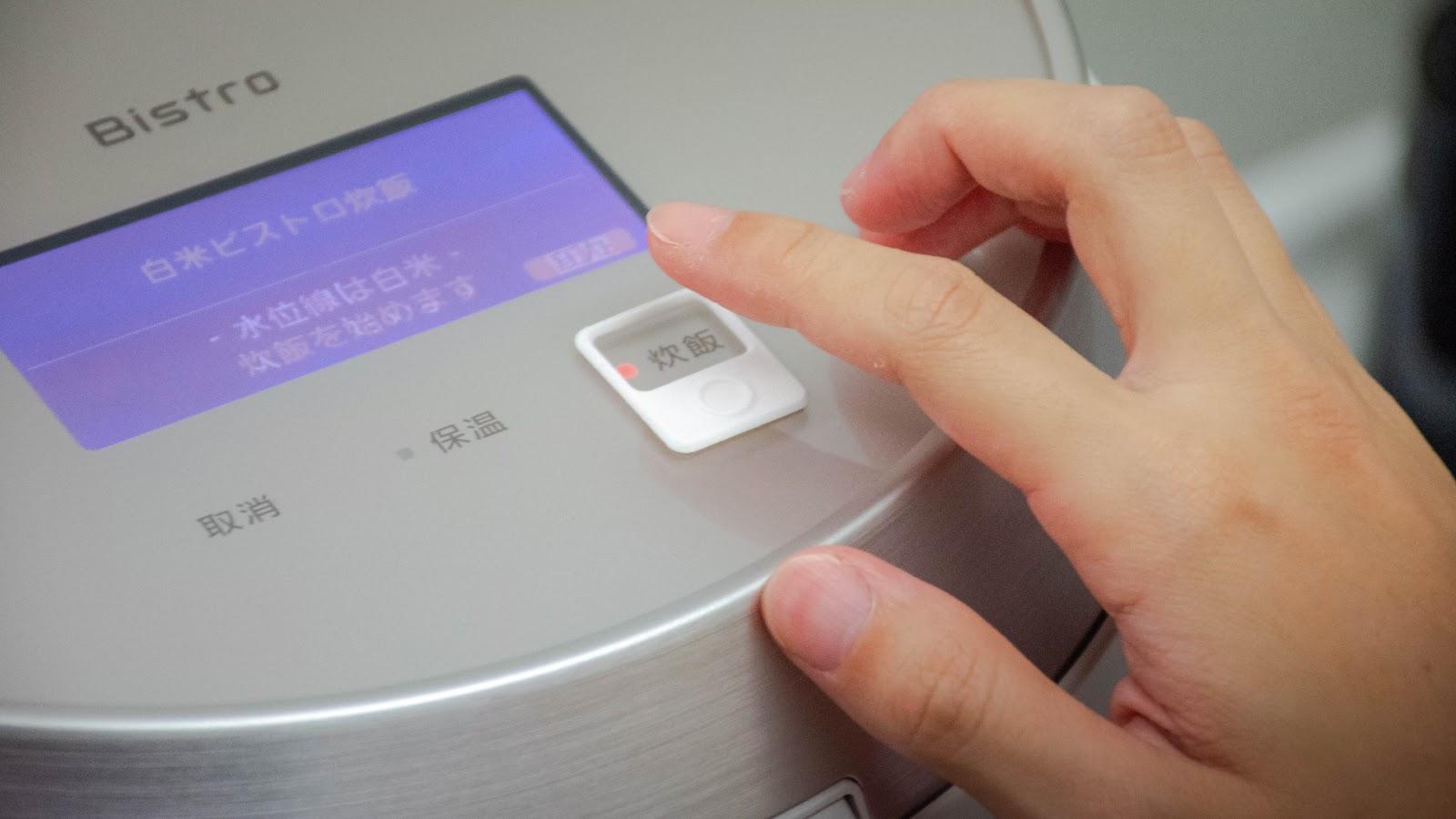
Example of attachment

*Precautions when attaching
- When attaching to a product with a heat source, such as a built-in induction (IH) cooktop, be sure to attach it so that the symbols are on the near side of the heat source, so that you do not accidentally bring your hand close to the heat source when checking the symbols. (Photo 1)

- If there is a lamp near the button that indicates the operating status, attach the chip so that it does not hide the lamp. (Photo 2)
- Also, attach it so that it hides the displays as little as possible.

Step 7.
Checking operation
Check that the operation buttons work normally even with the chip attached, and that the chip does not shift easily when touched with a finger. *If the operation buttons are hard to operate or the chip shifts easily, reattach it or replace it with a different chip.
Safety Precautions (Be sure to follow them)
This section explains what must be observed in order to prevent harm to people and damage to property. ■ It classifies and explains the degree of harm or damage that may result from incorrect use.

|
Content that may result in death or serious injury. |

|
Content that may result in minor injury or damage to property. |
■ What must be observed is explained with the following symbol.

|
Content describing what you must not do. |

|
|
|

|
|
|
 STOP Accidental ingestion  Store out of the reach of children |